Published 2026-10-05 · Updated 2026-09-30 · By Arclumin Team
Uneven LED display colors can come from the content, settings, calibration, or hardware. Learn how to narrow down the cause before changing parts.
Begin with the Pattern of the Difference
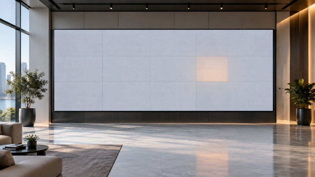
An LED wall that looks pink on one side or shows a brighter replacement module does not automatically need new LEDs. Uneven colour can begin in the video source, the control settings, the calibration data, or the physical display. The shape and timing of the difference are useful clues, but neither is a diagnosis on its own.
Start by recording whether the problem affects the whole image, one cabinet, a module, or individual pixels. Note whether it appeared after a content change, a repair, an update, or a long period of use. A clear description helps the service team choose a useful test instead of changing several settings at once.
Separate the Source from the Screen
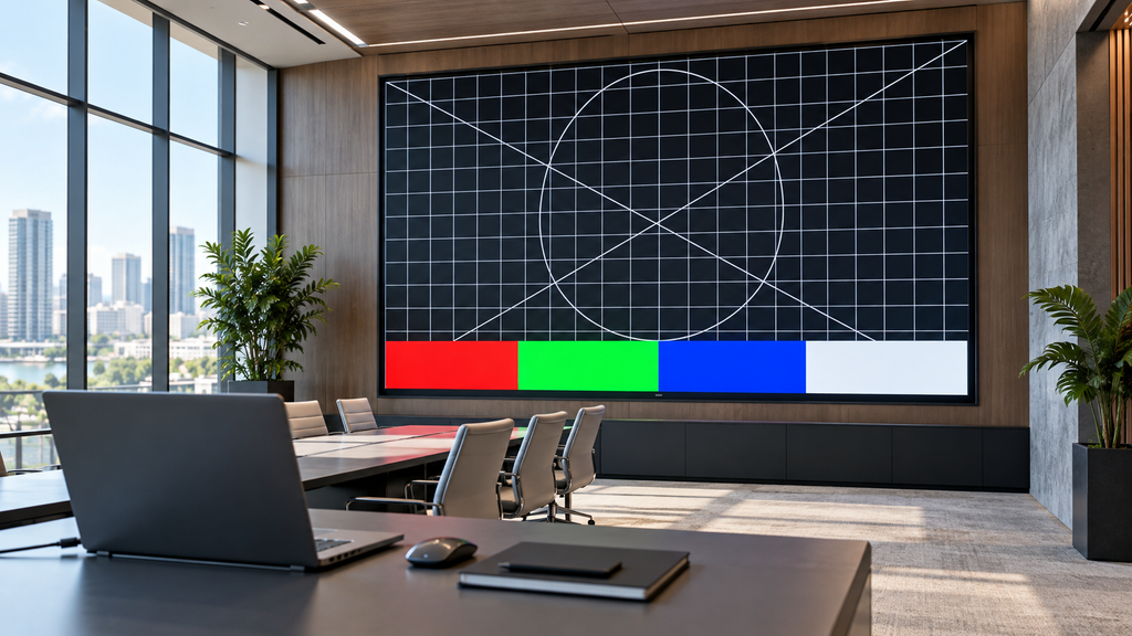
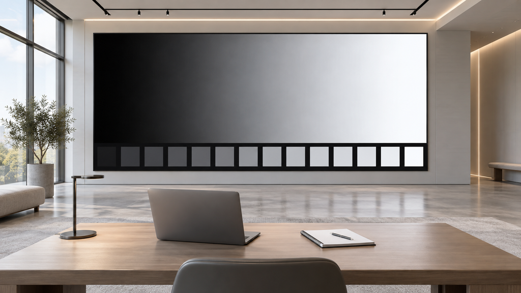
Use a known test image with neutral grey, white, and separate red, green, and blue areas. Check the original file on a suitable reference display and compare another known source when practical. A colour cast already present in a video should not be corrected by changing the entire LED wall to compensate for that one file.
Ask the operator to compare the source output and processor settings, including colour space, signal range, and any image adjustments. These need to agree across the signal chain. If only one input looks wrong, investigate that input path first; if every input shows the same cabinet-shaped patch, the display configuration or hardware deserves closer attention.
Keep the original operating settings before testing. Record the source, input, brightness, and time of each comparison so that a later result can be reproduced. Phone pictures are useful for locating a patch, but automatic exposure and white balance make them unreliable for measuring its exact colour.
Check the Conditions of the Comparison
Look at the screen from the intended audience position, then compare the affected area from a similar angle. Reflections, uneven room lighting, and different viewing angles can change the appearance of adjacent surfaces. A photograph taken very close to one corner may exaggerate a difference that is much less visible during normal use.
Use the usual operating brightness as well as a suitable test setting approved by the supplier. A wall that looks consistent at one level can reveal differences at another. Allow the equipment to reach its normal operating condition as specified for the installation, rather than deciding from the first seconds after power-up.
Compare Configuration and Calibration Data
Receiving cards need the correct configuration for the connected modules, and compatible systems can also use brightness or chroma calibration data. Configuration describes how the hardware is driven; calibration compensates for measured differences. Loading the wrong file or losing the relevant correction data can leave a visible boundary even when the replacement hardware works.
For a compatible NovaStar installation, the NovaLCT configuration manual explains the relevant configuration and calibration functions. The available options depend on the receiving card, module, and software version. A technician should back up the working files and identify the correct cabinet or module data before applying changes.
Do not upload a file simply because it came from a nearby cabinet. Similar-looking panels can use different components or settings. Also avoid a factory reset as the first experiment: it can remove the known working baseline and create additional faults that obscure the original colour problem.
Investigate Replacements and Physical Faults
A new module may differ from older surrounding modules because of component selection, production batch, accumulated use, or missing calibration. Matching the nominal pixel pitch and outside dimensions is not enough. Confirm the exact part and electrical compatibility, and ask how its calibration data will be integrated into the existing wall.
If a primary colour is missing, a patch flickers, or the fault changes with operation, the service team may need to investigate connections, power delivery, driver circuitry, or LEDs. These symptoms can overlap, so visual inspection alone cannot identify the failed component. Internal inspection and electrical measurements belong to trained personnel following the product service procedure.
Know What Calibration Can Achieve
Calibration can improve uniformity when supported by the equipment and suitable measurement tools. It does not repair damaged LEDs, restore a missing signal connection, or make every mixed component set equivalent. The achievable result can be limited by the weaker parts of the assembled display, so a technician should explain the expected result before work begins.
For an indoor fixed project using SG Steady Glow, keep the exact configuration and service records with the installation. The series name identifies the product family; it does not replace the model-specific file or guarantee that any spare module from that family can be interchanged. Record replacement dates and part identifiers to make later colour comparisons more useful.
Verify the Result and Preserve the Baseline
After a correction, repeat the original test with the same source, brightness, and viewing position. Check neutral greys, primary colours, darker gradients, and the content the customer actually uses. Look across cabinet seams and replacement areas rather than judging only a bright, colourful demonstration video.
Save the approved settings and calibration backup with a dated service note. State what changed and whether any remaining difference requires parts or further measurement. For corporate and control-room displays, include the normal presentation or monitoring sources in acceptance checks so that uniformity is assessed under real operating conditions.
For project inquiries, please contact your dedicated Arclumin Sales Consultant. Our team operates across time zones to support projects in Europe, North America, Africa, Australia, and markets worldwide.
WhatsApp +86 136 8235 1211 · 7×24 — we reply within 24 hours.

 SG Steady GlowIndoor Fixed LEDP1.25 – P4
 PL Pure LightIndoor Fixed LEDP1.25 – P1.86COB Fine Pitch LED→
 OG Obsidian GlowCOB Fine Pitch LEDP0.7 – P1.86View all product series →Not sure which series fits your project? Get a Recommendation →