Sending Card vs Receiving Card for LED Displays: What You Need to Know
Published 2026-10-08 · By Arclumin Team
Sending cards and receiving cards perform different jobs in an LED display system. Learn how to compare their roles and check a compatible configuration.
Follow the Image from the Source to the LEDs
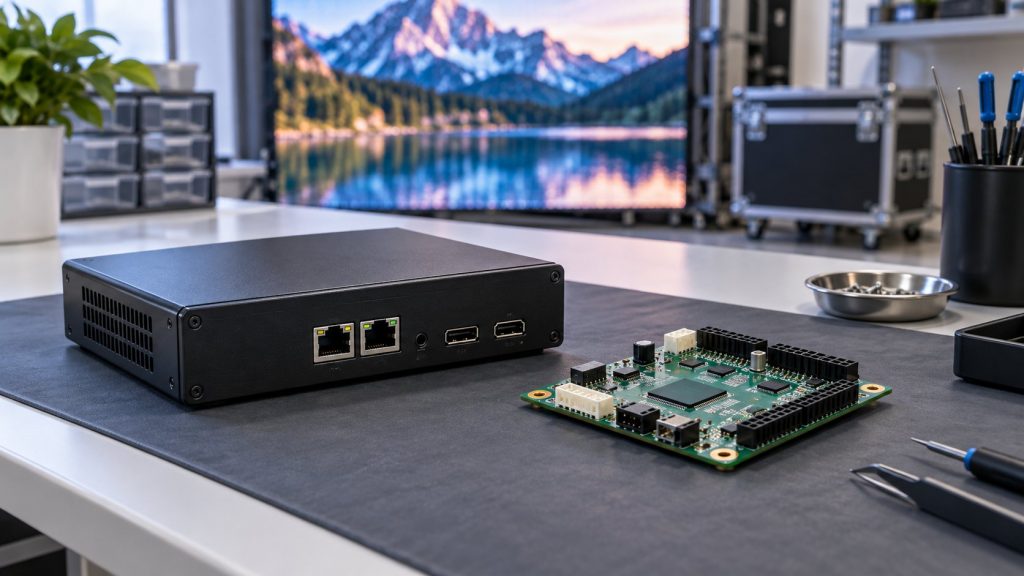
The simplest way to understand an LED control system is to follow the picture. A computer, media player, or camera provides the source; sending equipment distributes the display data; receiving cards inside the display pass the appropriate information toward the module drivers. Each stage has a different responsibility, even when several functions share one enclosure.
A sending card and a receiving card are therefore not two sizes of the same interchangeable part. Buying one with a higher advertised capacity does not automatically improve the other. The useful comparison is what each device does, what equipment it supports, and whether the complete combination meets the intended screen layout and operating conditions.
What the Sending Side Does
The sending side takes the relevant image data and distributes it through its supported output ports to the display. Depending on the product, it may be a separate card, a dedicated sending box, or part of an integrated video controller. Product names differ between manufacturers, so read the actual functions instead of deciding from the word card alone.
Video processing is a related but separate function. Some equipment also scales the picture, switches inputs, or combines layers, while a simpler sender may rely on other devices for those tasks. Check the source connectors, supported input formats, output arrangement, and required processing features before choosing a model.
What a Receiving Card Does
A receiving card is normally associated with a cabinet or another defined part of the display. It receives the data assigned through the screen connection layout and works with the cabinet electronics to drive the connected modules. The appropriate receiving-card configuration depends on the module and driver arrangement, not just the outside size of the cabinet.
Some receiving cards support calibration data, monitoring, redundancy, or other advanced features. These capabilities are model-dependent and can also depend on the sender, module hardware, firmware, and software. Do not assume that a feature listed for one receiver is available on another receiver from the same brand.
The NovaLCT configuration manual available in Arclumin’s downloads provides an example of screen connection and receiving-card configuration workflows for compatible NovaStar systems. It is a reference for supported equipment, not a universal instruction book for every LED controller. Keep the project-specific configuration supplied with the screen.
Compare Capacity Using the Actual Layout
Calculate the screen’s pixel dimensions from the selected cabinet arrangement, then check the proposed controller and receiving cards against that layout. Total pixels are only one part of the check. The allowed width and height, loading per output, receiving-card limits, and operating format can all constrain the usable arrangement.
For example, two screens with the same total pixel count can have different widths and cable routes. One may fit a proposed configuration while the other does not. Avoid multiplying a headline maximum width by a headline maximum height and assuming that the resulting rectangle is supported; separate maximum figures need to be read with the model’s other limits.
Ask the supplier for a screen connection drawing that identifies outputs, cabinets, and any reserved capacity. This makes the quotation easier to review than a statement that the controller supports enough pixels. It also gives the installer and future service team a common reference.
Check Compatibility Before Ordering Parts
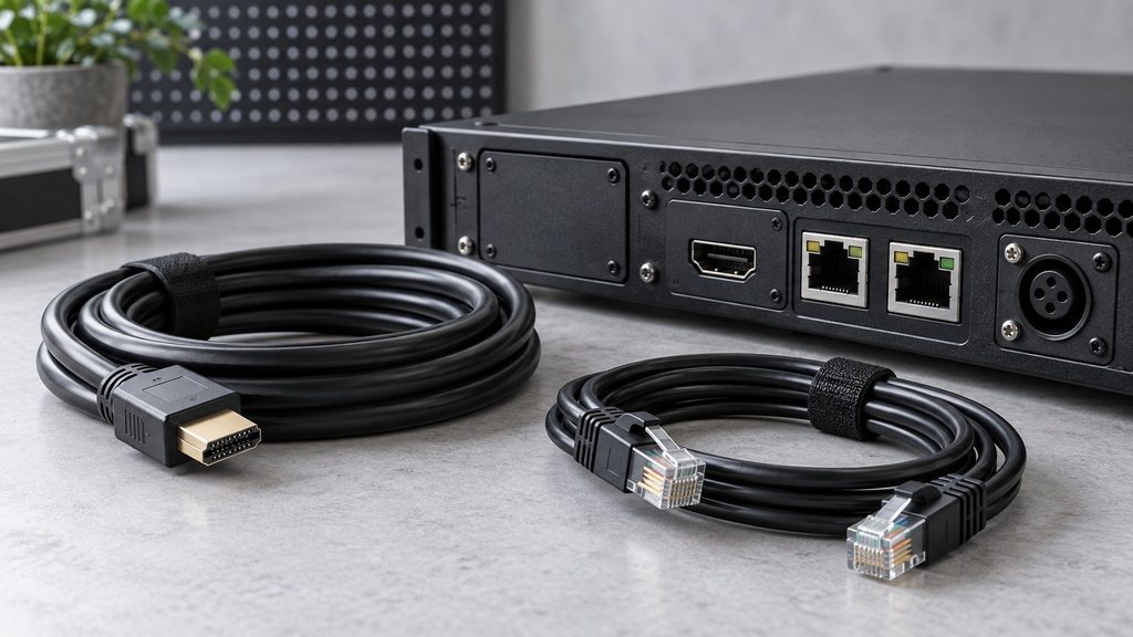
Confirm the sender and receiver models, their supported protocol or ecosystem, the module hardware, and the approved firmware combination. A matching network connector does not establish compatibility. Display data connections should not be treated as ordinary office network links unless the equipment documentation explicitly supports the proposed arrangement.
For a TL Traveling Light rental screen, request the exact configured control-system list with the cabinet order. The display series does not specify one universal receiving card for every project. A spare receiver should be selected against the delivered hardware and configuration, including any supported calibration or backup requirements.
Understand Configuration and Backup
Screen connection mapping determines which part of the image appears on each cabinet. Receiving-card parameters describe how the connected hardware operates. An incorrect mapping may rearrange the picture, while an incorrect hardware configuration can produce a different set of faults; both need their own checks.
Before replacing a receiver or changing settings, have the technician preserve the working configuration and relevant calibration data. Use the software version approved for the system, even if a newer installer is available. A firmware update should solve a defined compatibility or service need and include a recovery plan, rather than being the first response to every display fault.
Backup also needs precise language. Spare parts kept in a case are different from configured signal redundancy that can maintain a picture during a supported failure. Ask which components and routes are protected, what happens during a fault, and how the backup will be demonstrated at acceptance.
Test the Complete System Before Handover
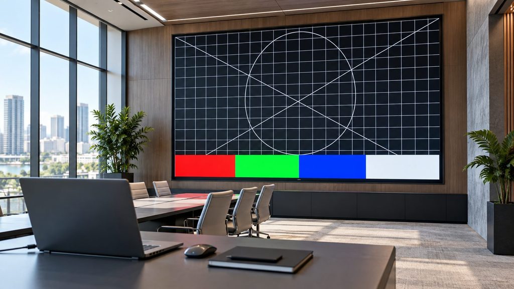
Use the actual sources and intended screen layout to test the delivered system. Check a mapping pattern, normal content, input changes, and any agreed backup behaviour. Confirm that the operator can restore the approved settings and identify the correct documentation without guessing which file belongs to which cabinet.
For rental and live-event applications, include the real cable plan and expected source changes in the test. A successful small bench demonstration does not validate every larger layout. Keep the equipment list, connection map, saved files, and service contacts together for the next deployment.
The simplest way to understand an LED control system is to follow the picture. A computer, media player, or camera provides the source; sending equipment distributes the display data; receiving cards inside the display pass the appropriate information toward the module drivers. Each stage has a different responsibility, even when several functions share one enclosure.
A sending card and a receiving card are therefore not two sizes of the same interchangeable part. Buying one with a higher advertised capacity does not automatically improve the other. The useful comparison is what each device does, what equipment it supports, and whether the complete combination meets the intended screen layout and operating conditions.
What the Sending Side Does
The sending side takes the relevant image data and distributes it through its supported output ports to the display. Depending on the product, it may be a separate card, a dedicated sending box, or part of an integrated video controller. Product names differ between manufacturers, so read the actual functions instead of deciding from the word card alone.
Video processing is a related but separate function. Some equipment also scales the picture, switches inputs, or combines layers, while a simpler sender may rely on other devices for those tasks. Check the source connectors, supported input formats, output arrangement, and required processing features before choosing a model.
What a Receiving Card Does
A receiving card is normally associated with a cabinet or another defined part of the display. It receives the data assigned through the screen connection layout and works with the cabinet electronics to drive the connected modules. The appropriate receiving-card configuration depends on the module and driver arrangement, not just the outside size of the cabinet.
Some receiving cards support calibration data, monitoring, redundancy, or other advanced features. These capabilities are model-dependent and can also depend on the sender, module hardware, firmware, and software. Do not assume that a feature listed for one receiver is available on another receiver from the same brand.
The NovaLCT configuration manual available in Arclumin’s downloads provides an example of screen connection and receiving-card configuration workflows for compatible NovaStar systems. It is a reference for supported equipment, not a universal instruction book for every LED controller. Keep the project-specific configuration supplied with the screen.
Compare Capacity Using the Actual Layout
Calculate the screen’s pixel dimensions from the selected cabinet arrangement, then check the proposed controller and receiving cards against that layout. Total pixels are only one part of the check. The allowed width and height, loading per output, receiving-card limits, and operating format can all constrain the usable arrangement.
For example, two screens with the same total pixel count can have different widths and cable routes. One may fit a proposed configuration while the other does not. Avoid multiplying a headline maximum width by a headline maximum height and assuming that the resulting rectangle is supported; separate maximum figures need to be read with the model’s other limits.
Ask the supplier for a screen connection drawing that identifies outputs, cabinets, and any reserved capacity. This makes the quotation easier to review than a statement that the controller supports enough pixels. It also gives the installer and future service team a common reference.
Check Compatibility Before Ordering Parts
Confirm the sender and receiver models, their supported protocol or ecosystem, the module hardware, and the approved firmware combination. A matching network connector does not establish compatibility. Display data connections should not be treated as ordinary office network links unless the equipment documentation explicitly supports the proposed arrangement.
For a TL Traveling Light rental screen, request the exact configured control-system list with the cabinet order. The display series does not specify one universal receiving card for every project. A spare receiver should be selected against the delivered hardware and configuration, including any supported calibration or backup requirements.
Understand Configuration and Backup
Screen connection mapping determines which part of the image appears on each cabinet. Receiving-card parameters describe how the connected hardware operates. An incorrect mapping may rearrange the picture, while an incorrect hardware configuration can produce a different set of faults; both need their own checks.
Before replacing a receiver or changing settings, have the technician preserve the working configuration and relevant calibration data. Use the software version approved for the system, even if a newer installer is available. A firmware update should solve a defined compatibility or service need and include a recovery plan, rather than being the first response to every display fault.
Backup also needs precise language. Spare parts kept in a case are different from configured signal redundancy that can maintain a picture during a supported failure. Ask which components and routes are protected, what happens during a fault, and how the backup will be demonstrated at acceptance.
Test the Complete System Before Handover
Use the actual sources and intended screen layout to test the delivered system. Check a mapping pattern, normal content, input changes, and any agreed backup behaviour. Confirm that the operator can restore the approved settings and identify the correct documentation without guessing which file belongs to which cabinet.
For rental and live-event applications, include the real cable plan and expected source changes in the test. A successful small bench demonstration does not validate every larger layout. Keep the equipment list, connection map, saved files, and service contacts together for the next deployment.
For project inquiries, please contact your dedicated Arclumin Sales Consultant. Our team operates across time zones to support projects in Europe, North America, Africa, Australia, and markets worldwide.
WhatsApp +86 136 8235 1211 · 7×24 — we reply within 24 hours.

 SG Steady GlowIndoor Fixed LEDP1.25 – P4
 PL Pure LightIndoor Fixed LEDP1.25 – P1.86COB Fine Pitch LED→
 OG Obsidian GlowCOB Fine Pitch LEDP0.7 – P1.86View all product series →Not sure which series fits your project? Get a Recommendation →